1. Introduction
It is so said that Symbulator has its capability limited to linear circuits. Someone who only get knowing Symbulator after taking circuit analysis class might be disappointed since now they are dealing with BJT or MOSFET now, both are non linear components, but I'll show you how to use Symbulator in analog circuit class, since a lot part of BJT and MOSFET biasing homework problems is still about solving linear systems of equations. And this is better than using simulators since most of the time the operating characteristics of the transistors are made up or given as rounded values.
2. Four resistors BJT biasing
When it comes to 4R, it always involves some circuit analysis, or you have to memorize many equations to speed up calculation. I'm the type of person that hardly remembers any formulas, so using Symbulator is the better alternative to me. Besides, usually it involved computing parallel impedance a lot, and it is not easy to do that on even programmable calculators unless it has equipped a very fancy programming language combined with a good keyboard.
A common type of problem would be asking for Q-point. Usually the VBE is given, I would assume 0.7V here since that is a common value been used.
And for most of the time the transistor would be assumed in forward active region (if it is MOSFET that would be saturation, but I would cover that later in the article). Just make sure to check the forward active condition after solved Q-point.
Lets look up for some examples. Assume β = 75, find the Q-point of NPN Q1.
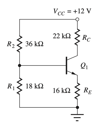
It is fairly easy to come up with a netlist using dependent
current source that forces IC to be β
times IB and an independent voltage
source for VBE:
|e1,1,0,12|:r2,1,2,36'k|:r1,2,0,18'k|:r4,1,3,22'k5 |:j1:3,4,75*(ir2-ir1)|:e2,2,4,0.7|:r3,4,0,16'k
Then use DC analysis. The solved pair {ij1,vj1} is
the Q-point, and result is {0.000201547 4.29820847},
which matches the "accurate result" (202μA, 4.30V) given in the
book.
Another common type of problem is giving the Q-point and ask for the value of resistors.
Using a 15V supply with an NPN having β=100, deisgned for a bias circuit giving Q-point of (75μA, 5V). (taken from Jaeger & Blalock, excersie part of example 5.9)
Hint: it is implied that resistors RE and RC have equal voltage, that is, each has 5V.
Now, solving for RC and
RE are fairly easy, they can be
calculated by divide voltage by IC and
IE. We are more interested in how to
get R1 and R2.
To solve this we could use the ex tool, but first
we need the netlist:
|e1,1,0,15|:r2,1,2,x2'k|:r1,2,0,x1'k|:e2,2,0,5.7
We would also need additional constrains ir2-ir1=75E-6/100
and ir2=75-6/10, and unknowns x1,x2. The solved
results are x1=1240000, x2=844444.444, which matches
the book answer.
3. Small signal model gain
After biasing, a common problem would be convert the circuit to hybrid-pi model and compute the gain. This would be not easy if original circuit has no capacitor in parallel with RE, like this figure, assume Early voltage be infinity, β=100.
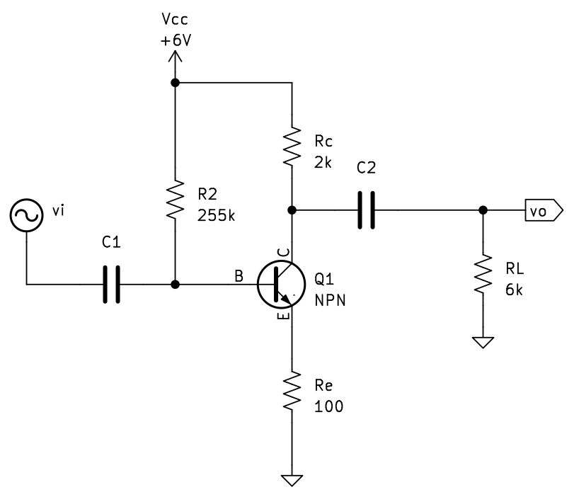
We can compute gm to be 80mS and
Rpi is 1.25㏀.

It is then time to through the circuit to Symbulator. Assume source current to be 1 to save some time on solving.
|e1,1,0,1|:r2,1,0,255'k|:rp,1,2,1250|:re,2,0,1005 |:j1,3,2,0.08*vrp|:rcc,3,0,2'k|:rl,3,0,6'k
Since it is a resistance only circuit, DC analysis is good
enough. The output voltage gain is equal to VRL which is -13.2159, current gain is -IRL/IE1=-23.935.
4. MOSFET biasing
When using MOSFET for amplifier, it is operating in the saturation mode, that is V(DS) > V(GS) - V(TH) > 0 for NMOS, and we usually just assume gate current to be zero, so the resistor connected to the gate would not contribute to the biasing, but the gate voltage would be the same as the voltage source connected to the gate through the resistor.
Thus MOSFET is thus easier to define since it would just be a current source that is dependent on the voltage across itself.
However, since there is quadratic equation involved rather than only linear equations, there could be multiple solutions and you might want to use expert mode to add additional conditions.
Bibliography
[Jaeger & Blalock] Microelectronic Circuit Design. 5th. 256-257, 259-260.