1 Introduction
This laboratory experiment introduces the basic operation of TIMS and how to generate function signals with S&S SFP software and measuring waveform with PicoScope digital scope.
2 Procedures
2.1 Part A: PC-MODULES CONTROLLER and PicoScope
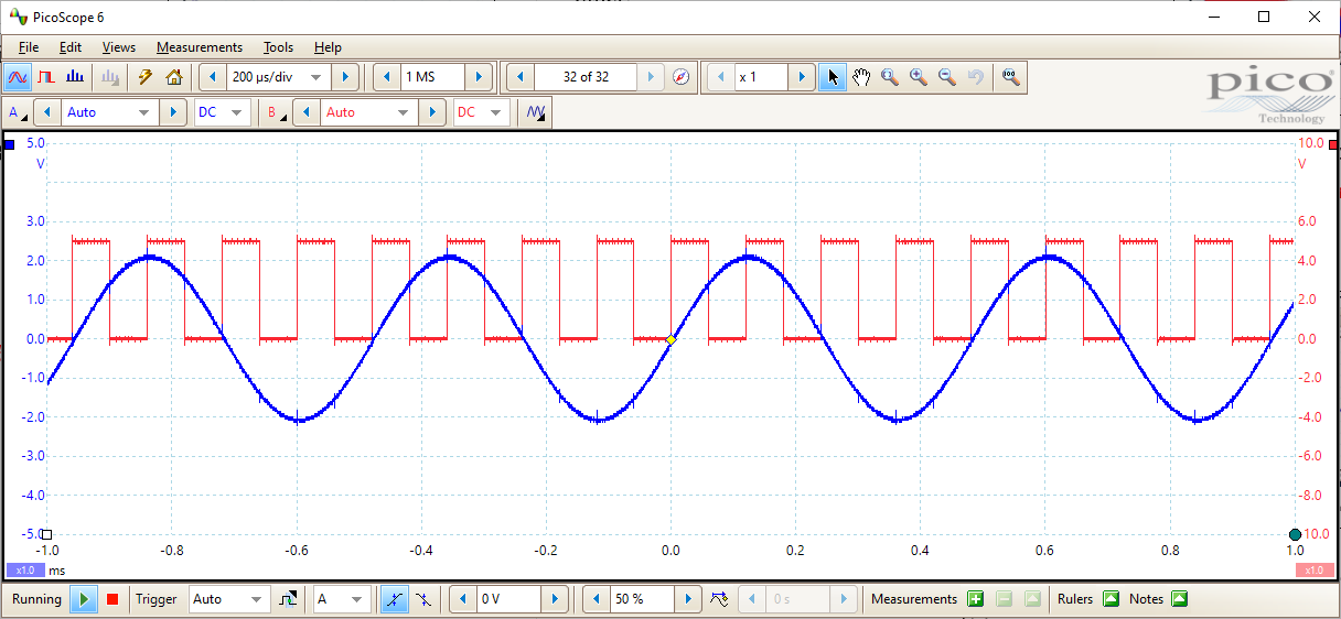
This part has setup measuring the 2kHz MESSAGE signal (sine wave) on Channel A and 8.3kHz SAMPLE CLOCK (square wave) on Channel B to demonstrate the basic usage of PicoScope, including stabilize the signal by setting up Auto Trigger, scaling of the signal on the scope.
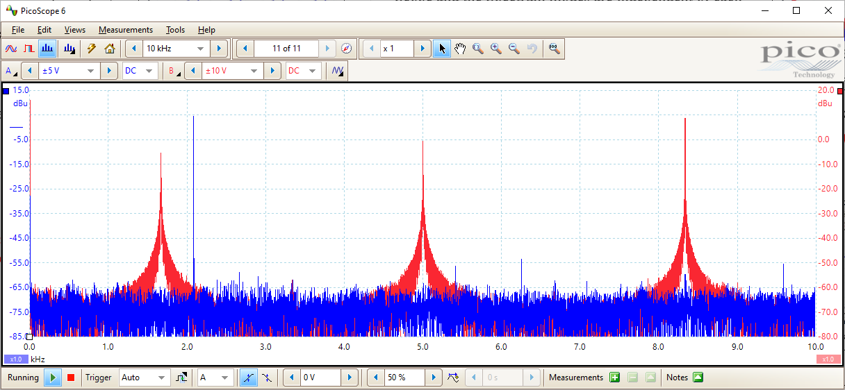
Shown in Figure 2.1.2, Spectrum view of channel A and channel B is the corresponding frequency spectrum view of two channels.
2.2 Part B: Triggering
Triggering is a setup parameter of oscilloscope that when updating the scan of the signal on the screen, ensure the amplitude of the start point and the phase of the sinusoid is same to provide a stabilized display.
2.3 Part C: TIMS S&S SFP
This part demonstrates how to used the SFP to generate signals, and the PicoScope picks up the same waveform displayed on the ARB Viewer.
2.4 Part D: SFP Control of TRIPLE ADDER Gains
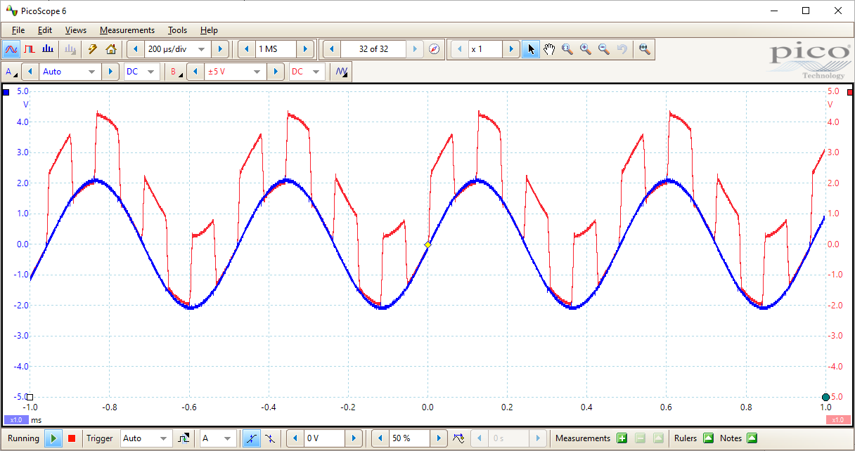
The TRIPPLE ADDER module can adds up to three input signals to the output port. TIMS S&S SFP can also control the multiply factor of each input signal.
This setup has connected the 2kHz MESSAGE to input a0 and the 8.3kHz SAMPLE CLOCK to a1, with the multiply factor 1 and 0.5. The result is in Figure 2.4.1, Comparing channel A and channel B.
3 Conclusion
This introductory is fun to me because operating TIMS has generated a lot of vibes from using analog modular synthesizer from my experience with electronic music. The instruction did confused me a little bit because the label on the TIMS workstation I used is not exactly the same to the description. I think the simplification of the instruction is possible if the connection between ports can be more terse.