1 Introduction
This lab further explores the transformation we can do in TIMS. We would investigate and analysis the input/output linearity relation of these systems. VCO, Multiplier, Variable DC and Laplace V2 are the new modules that would be introduced in this lab.
2 Procedures
2.1 Linearity: scaling
2.1.1 Comparator
The comparator module would convert the analog input signal to a binary output. In this experiment we use the VCO module to generate a sine wave, and control its amplitude via Buffer Amplifiers, then pass through the comparator from Utilities TIMS module.
The input/output relation can be seen in Figure 2.1.1.1, Comparator output voltage response to changing input peak to peak voltage.. Since scaling has little impact to the output, the system should be considered as linear.
2.1.2 Rectifier
The Rectifier module would preserve only the positive part of the voltage signal, and its input/output relation is depicted in Figure 2.1.2.1, Rectifier output voltage response to changing input peak to peak voltage..
It appears that this is a linear system, since the Vpp of the output is same to the input which indicates it satisfies the scaling property.
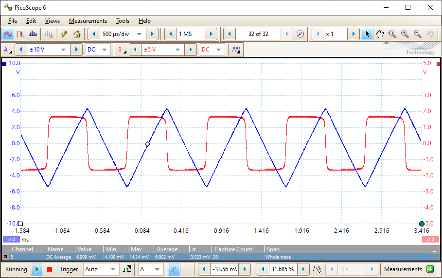
2.1.3 Multiplier
Simply as its name suggests, Multiplier outputs the product of its two input signals. In this experiment we use the amplified VCO output for the X and Y input signal to the Multiplier. This means the output would be the squared input.
Clearly that the signal demonstrates exponential function behavior and does not satisfies the properties of a linear system.
Note that the output signal is actually 1/2 of the squared input, instead of matching the half angle formula in the lab introduction. According to the TIMS manual, it is designed so to avoid overloading later stages.
| Input Amplitude | Output Amplitude |
|---|---|
| 0.536 | 0.0635 |
| 1.073 | 0.284 |
| 1.521 | 0.559 |
| 2.076 | 1.1795 |
| 3.042 | 2.4915 |
| 4.026 | 4.288 |
2.2 The VCO as a System
2.2.1 DC Control
This part shows how to use a DC variable input to control the frequency of the VCO module. The relation between the DC voltage input and the output frequency of the VCO is shown in .
| DC value (V) | Signal frequency (Hz) |
|---|---|
| -2 | 4150 |
| -1 | 3520 |
| 0 | 2900 |
| 1 | 2320 |
| 2 | 1800 |
2.2.2 Frequency Control
For this part, instead of using a DC input we would use a sine wave for input control. This is called modulation.
The input/output relation corresponds to the result from last section: when the input voltage is at high point the output frequency drops.
One obvious application of this type of system is FM radio.
2.3 Feedback System
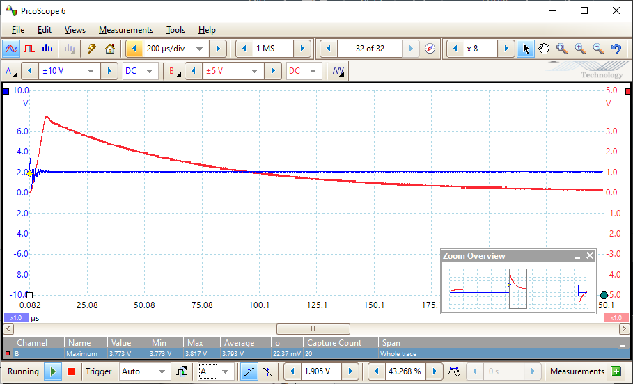
2.3.1 Integrator
The LAPLACE V2 module provides an integrator that sums the area under the input signal. A square wave produced from the comparator is integrated.
In Figure 2.3.1.1, Integrator, channel A which is a saw tooth wave is the integrated channel B, a square signal.
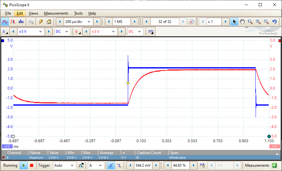
2.3.2 Feedback System
We would build a feedback system and compute the step response of the system.
The input signal is integrated and then the inverted integrated signal is looped to the input of the integrator.
According to Figure 2.3.2.1, Triple adder output, the time constant is about 72.17 micro seconds. Figure 2.3.2.2, The integrator output is the integrated response.
3 Conclusion
The most interesting part I learned in this lab is how to produce a saw tooth wave from a square wave using integrator, which is one of the very fundamental parts of a electronic sound synthesizer.
In the part that uses the triple adder, I had problem that the output response does not match the expected one. Then I located the problem seems to be the triple adder is not properly connected to the TIMS rack, so it is not receiving configuration from the software.
For future improvements, I suggests we can add a few test cases to trouble shoot the triple adder if the connectivity issue happens again.