1 Introduction
This lab would be focusing on using Z-transform module. Applying Z-transform to unit step signal would results in unit delay, and by adding multiple delayed signal together the result is equivalent to convolution.
2 Procedures
2.1 Setting up
The 8.33kHz TTL Master Signals is divided by 8 using Digital Utilities module which results in an approximately 1kHz signal, used as the CLK input of the Sequence Generator.
The SYNC output from the Sequence Generator is amplified to 1V.
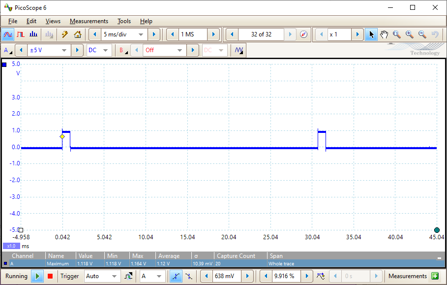
According to TIMS manual the SYNC output indicates the start of a random sequence generated by Sequence Generator, and the default length is 32, thus the output is 1 pulse every 32 periods, shown in Figure 2.1.1, Sync function output.
2.2 Unit pulse response
Adding the original signal with delayed pulse signals results in
the Figure 2.2.1, Delayed input
signals. From left to right they are h[0], h[1],
h[2]. The summed output is in Figure 2.2.2, Added output
signals.
![h[0], h[1], h[2]](./lab8-p2.png)
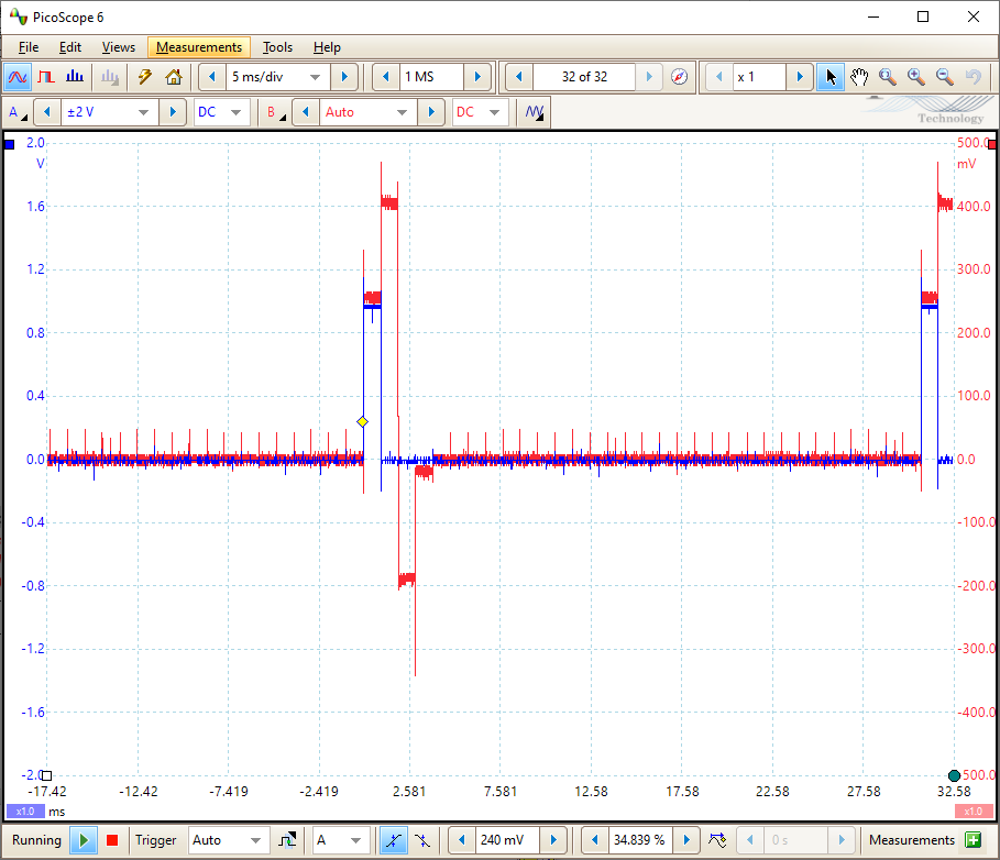
| Label | Input amplitude | Output amplitude |
|---|---|---|
| h[0] | 0.3 | 260mV |
| h[1] | 0.5 | 400mV |
| h[2] | -0.2 | -200mV |
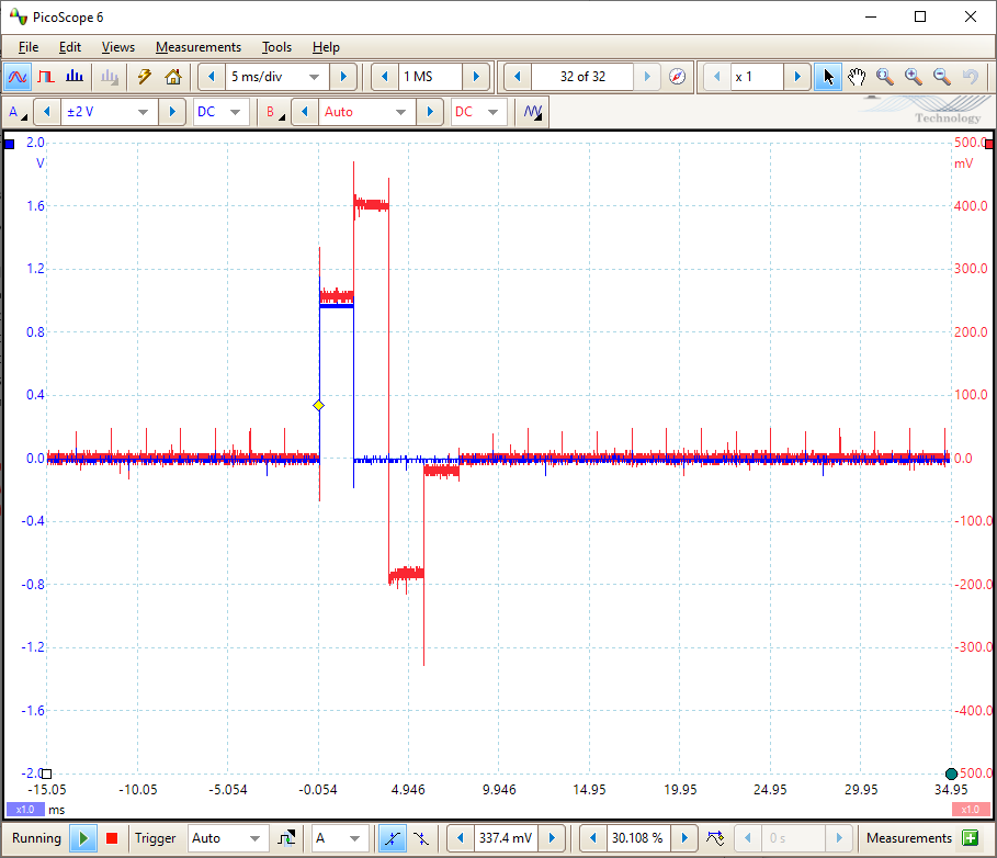
2.3 The superposition sum
In this part we extend the pulse width to twice of the original, and the resulted waveform should be the addition of original output to the signal one step delayed.

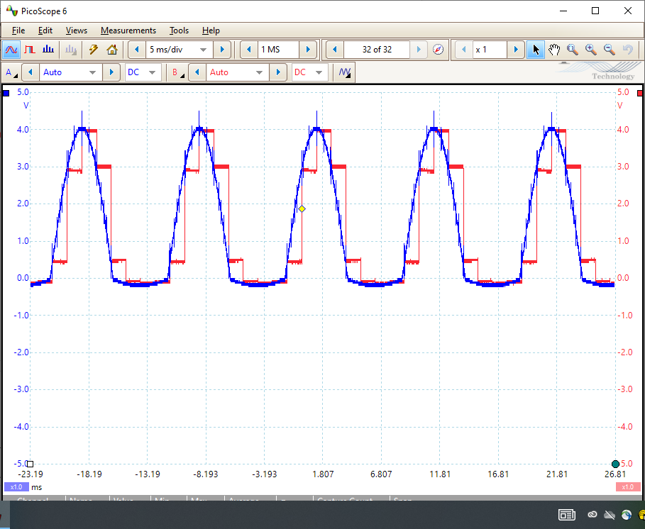
2.4 Rectified sine-wave at input
In this part we would input a sequence of pulses of different amplitude to observe the feedback from the same system.
As shown in Figure 2.4.1, ARB1 frequency and Vpp, the peak-to-peak voltage is 2V and frequency is about 100Hz.
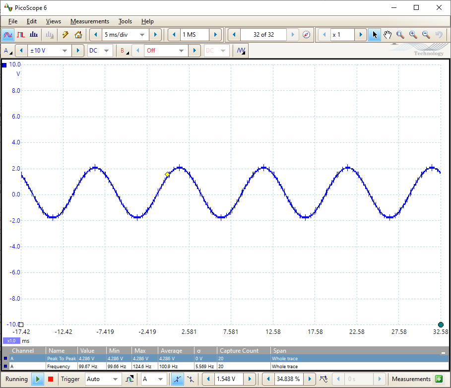
The rectifier used is a full-wave precision rectifier so the output amplitude is twice as the input.
Sample and Hold basically did a quantization on the input by sampling at fixed time interval and hold the sampled voltage to the output to form a discrete signal.

3 Conclusion
In this lab the most interesting part to me would be the S/H function which I have seen as part of electronic synthesizer but had yet not learned how it works.
It is confusing which using the Z-transform module since the lab instruction did not say it needs a CLK input to properly work. Also the Z-transform module on my station was not functioning properly that I spent too much time troubleshooting that.