1 Introduction
This lab is a continuation of previous lab on using Z-transform module. We would derive the discrete convolution formula from the addition of weighted delayed signals.
2 Answer to questions
-
Superposition is that for a linear circuit the response of the sum of multiple input signals is equal to the sum of the response of individual input signals.
-
The convolution with delta function is the identity transform, since it is like take slices everywhere of the original signal and assemble them together.
3 Procedures
3.1 Unit pulse response
The system been setup in this part would output the original signal, the signal delayed for 1 unit time, delayed 2 unit time, each multiplies a different weight, then added them together.
The unit delay is achieved through the Z-transform module. The multiplication and addition is done by the Triple Adder module.
In real life, delayed energy is usually caused by capacitors.
3.2 The superposition sum
The desecrate convolution is the summation of the input signal treated as an array of weights times impulse function delayed.
If the input was four pulses back to back instead of two, it would be four unit pulse response delayed for 0, 1, 2, 3 unit time step and added together.
To simulate this, the divide by 4 port of Digital Utilities can be used to generate a 250Hz CLK signal to be used by Sequence Generator.
3.3 Rectified sine-wave at input
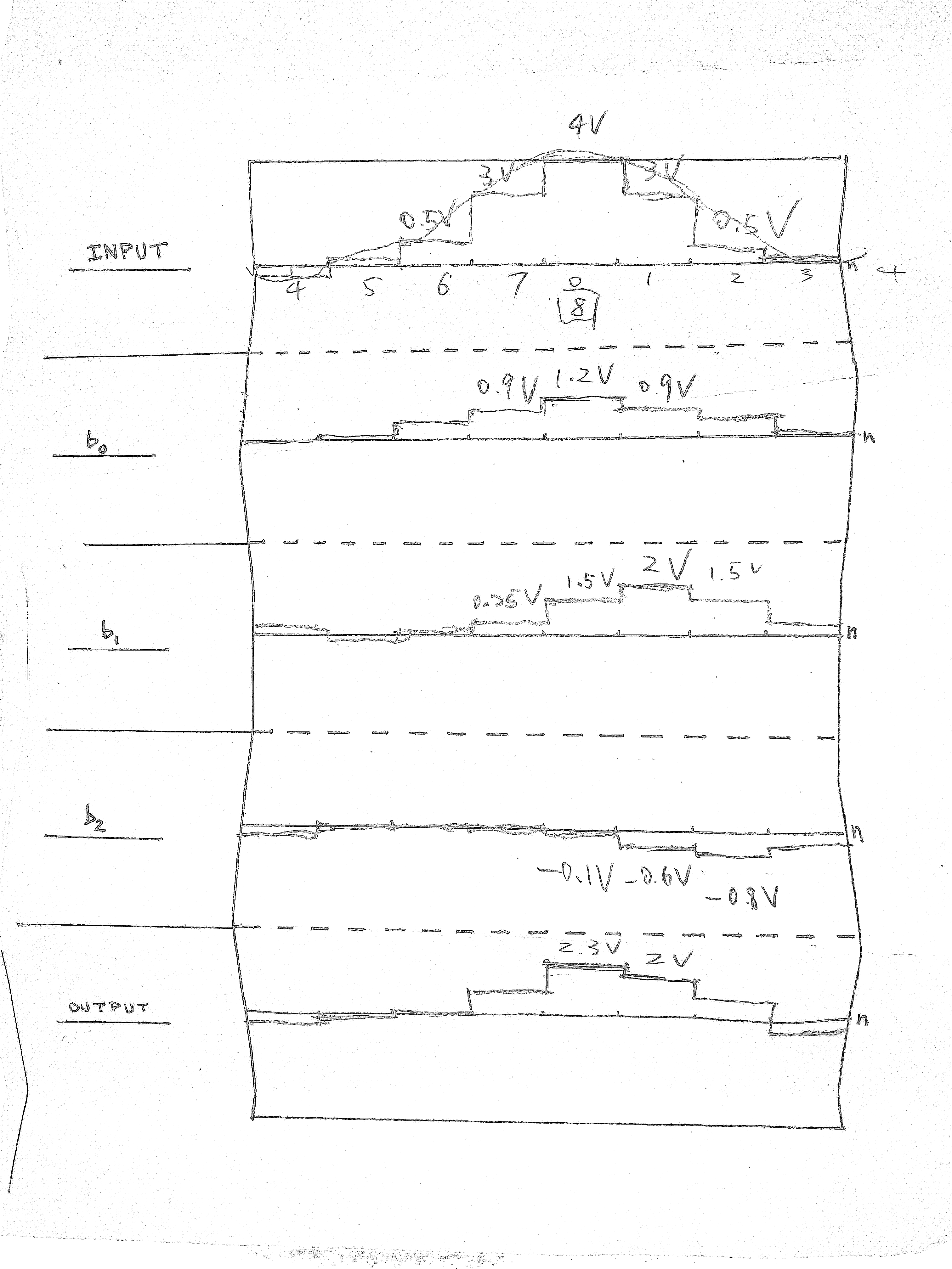
| Step | b0 | b1 | b2 | b0+b1+b2 | Output | Error |
|---|---|---|---|---|---|---|
| 1 | 1.2 | 1.5 | -0.1 | 2.6 | 2.3 | -0.3 |
| 2 | 0.9 | 2 | -0.6 | 2.3 | 2 | -0.3 |
| 3 | 0.15 | 1.5 | -0.8 | 0.85 | 1 | +0.15 |
4 Conclusion
In this lab the most interesting part to me is the discrete convolution which I have used in computing Gaussian blur of an image.
I found the expected output for a pulse signal of twice width a bit confusing, but this lab explains the expected result better. It might be more desired to rearrange this two lab assignments that all parts about superposition sum are in one lab and rectified sine-wave could be in another lab.